


When you hold a set of architectural plans in your hands, you’re looking at far more than lines on paper — you’re holding the blueprint of an entire vision. Whether you’re a homeowner planning a renovation, a contractor preparing for a new build, or an investor evaluating a property, understanding architectural plans is one of the most valuable skills you can develop. These technical drawings translate abstract ideas into precise, buildable realities and serve as the legal foundation for every construction project. In this comprehensive guide, we’ll break down everything you need to know about architectural plans, from their core components and types to the software professionals use and the common pitfalls that trip up beginners.
What Are Architectural Plans?
Architectural plans are detailed technical drawings that communicate the design, dimensions, materials, and spatial relationships of a building or structure. Also known as building plans, construction drawings, or design documentation, these drawings act as the universal language between architects, engineers, contractors, and clients. A well-drafted architectural plan set answers critical questions: How big is the building? What materials will be used? Where do the plumbing and electrical systems run? These documents are not just illustrations — they are legally binding construction documents that must comply with local building codes, zoning regulations, and permitting requirements. Without accurate architectural plans, even the most inspired design concept cannot become a physical structure.

Types of Architectural Plans
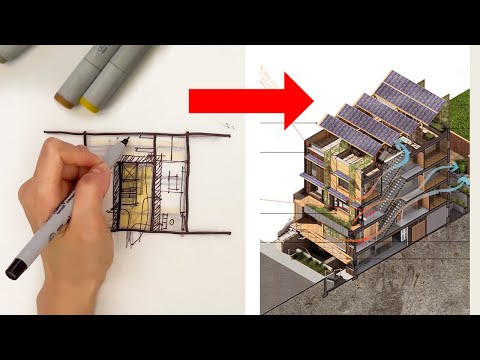
Not all building plans are created equal. A complete architectural plan set includes several distinct drawing types, each serving a unique purpose. Understanding these categories helps you communicate effectively with your architect or designer and ensures you receive everything you need for your project.
Floor Plans
Floor plans are the most recognizable type of architectural drawing. They provide a top-down, bird’s-eye view of each level of a building, showing room layouts, wall thicknesses, door and window placements, and furniture arrangements. Floor plans typically include dimensions, room labels, and notes about flooring materials. Whether you’re working on a single-story residence or a multi-story commercial building, the floor plan is the central document around which all other drawings revolve.
Elevation Plans
Elevation plans show the exterior faces of a building from specific viewpoints — typically the front, back, left, and right sides. These drawings communicate the building’s height, material finishes, window and door styles, roofline profile, and overall aesthetic character. Elevation plans are essential for obtaining building permits because they demonstrate how the structure will look within its surrounding environment and neighborhood context.
Site Plans
A site plan maps the entire property, including the building footprint, driveway, landscaping, utility connections, setbacks, and drainage patterns. Site plans incorporate topographic data, property lines, and municipal easements. They are critical for zoning compliance and for showing how the building fits within the broader landscape and infrastructure.
Section and Detail Drawings

Section drawings cut through the building vertically to reveal internal structural relationships — think of it as looking inside a wall or floor assembly. Detail drawings zoom in on specific connections, such as how a roof meets a wall or how a stair railing attaches to a post. These drawings provide the precision that general plans cannot convey.
Key Components of a Complete Architectural Plan
A professional architectural plan set includes several essential elements that work together to eliminate ambiguity during construction. Here are the components you should expect to find:
- Title block: Contains the project name, architect’s information, date, revision history, and scale.
- Scale bar and dimensions: Every drawing must include a scale reference and accurate measurements in consistent units.
- North arrow: Establishes orientation so contractors and inspectors know the building’s relationship to cardinal directions.
- Material callouts: Annotations specifying concrete grades, wood species, insulation R-values, and finish types.
- Legend and symbols: A key explaining the icons, line weights, and notations used throughout the set.
- Cross-references: Notes directing readers to related drawings within the plan set, such as “see electrical plan sheet 4.”
The Architectural Plan Creation Process
Creating architectural plans follows a structured workflow that balances creativity with technical precision. The process typically unfolds in several phases:
- Pre-design and programming: The architect meets with the client to discuss goals, budget, site constraints, and functional requirements. This phase produces a written program document that outlines room sizes, adjacencies, and desired features.
- Schematic design: Initial sketches and massing studies explore spatial concepts. The architect develops rough floor plans, elevations, and site layouts to establish the project’s direction.
- Design development: The chosen design is refined with more precise dimensions, material selections, and structural systems. Structural, mechanical, and electrical consultants begin contributing their input.
- Construction documentation: This is where the full plan set comes together. Drafters and architects produce detailed drawings, specifications, and schedules that contractors will use to bid and build. This phase often takes the longest and requires the most collaboration.
- Permitting and revisions: The plans are submitted to the local building authority for review. Comments from code officials may require revisions before a permit is issued.
Tools and Software for Drawing Architectural Plans
Modern architectural practice relies heavily on digital design tools that offer precision, collaboration, and visualization capabilities far beyond hand-drafting. Here is a comparison of the leading software platforms professionals use:
| Software | Primary Use | Key Strength | Best For |
| AutoCAD | 2D drafting and detailing | Industry-standard precision | Traditional plan sets and technical documentation |
| Revit | Building Information Modeling (BIM) | 3D parametric modeling with data integration | Complex commercial and institutional projects |
| SketchUp | 3D conceptual modeling | Intuitive, fast learning curve | Early design exploration and client presentations |
| ArchiCAD | BIM and architectural design | Integrated BIM from design to documentation | Architects focused on end-to-end workflow |
| Chief Architect | Residential design and home planning | User-friendly interface with built-in libraries | Homeowners, interior designers, and small firms |
Each tool has its strengths, and many firms use a combination of platforms to complete a single project. The trend in the industry is clearly moving toward BIM software like Revit, which allows architects to embed material properties, cost data, and performance metrics directly into the 3D model rather than managing that information separately in spreadsheets and specifications.
Common Mistakes to Avoid When Reading or Creating Plans
Even experienced professionals can stumble when working with architectural drawings. Here are some of the most frequent errors that lead to costly delays and construction problems:
- Ignoring scale: Assuming a dimension without verifying the drawing’s scale can result in materials ordered in the wrong quantities. Always check the scale bar before taking measurements from a printed sheet.
- Overlooking coordination between disciplines: Architectural plans must align with structural, mechanical, electrical, and plumbing drawings. Conflicts between these systems are one of the top causes of change orders on job sites.
- Using outdated revisions: Construction teams who reference an old version of a drawing can install components incorrectly. Always confirm you have the latest revision number stamped in the title block.
- Skipping code review: Plans that don’t account for local building codes — fire egress requirements, accessibility standards, energy codes — will be rejected during permitting and may create liability issues.
- Underestimating the need for details: General plans rarely communicate how complex assemblies should be constructed. Missing detail drawings lead to ambiguity and inconsistent workmanship.
Expert Tips for Working with Architectural Plans
Whether you are reading plans as a client or creating them as a professional, these practical recommendations will elevate your results:
- Always start with the legend. Every plan set includes a legend or key. Spend a few minutes understanding the symbols, line weights, and abbreviations before diving into the drawings themselves.
- Walk the plan spatially. Don’t just read dimensions — imagine walking through the space. This mental exercise reveals circulation problems, awkward adjacencies, and overlooked functional issues.
- Verify dimensional consistency. Check that dimensions referenced in one drawing match those in another. A window width listed in the floor plan should correspond to the same opening shown in the elevation.
- Invest in quality printing. Construction drawings are often printed on large-format paper at scales like 1:50 or 1/4″ = 1′-0″. Poor print quality can make fine lines illegible and cause misreadings on site.
- Keep a revision log. Maintain a physical or digital tracker of every revision made to the plan set so your team always works from the correct version.
Conclusion
Architectural plans are the backbone of every successful construction project. From the initial floor plan that defines a building’s layout to the detailed section drawings that specify how walls, roofs, and foundations connect, these documents transform creative vision into buildable reality. Understanding the types, components, and creation process behind architectural plans empowers homeowners, investors, and construction professionals alike to make informed decisions, avoid costly mistakes, and ensure their projects meet both design aspirations and regulatory requirements. Whether you are hiring an architect for the first time or managing a construction crew, treating these drawings with the attention they deserve is the single best investment you can make in your project’s success.
FAQs About Architectural Plans
How long does it take to create architectural plans for a residential project? The timeline varies significantly based on project complexity, but a typical residential plan set takes anywhere from 4 to 12 weeks from initial concept to final construction documents. Simpler renovations may be completed in under a month, while custom homes with complex detailing can take several months, especially if zoning approvals or structural engineering coordination are required.
Can I create my own architectural plans, or do I need a licensed architect? For minor renovations and simple structures, DIY plan software like Chief Architect or SketchUp can produce usable drawings. However, most municipalities require plans to be stamped by a licensed architect or engineer for permitting. Submitting unlicensed plans for a project that requires professional certification can result in permit rejection, fines, or legal liability if structural issues arise later.
What is the difference between architectural plans and blueprints? “Blueprint” is a legacy term that historically referred to a specific white-and-blue reproduction process used in the 19th and 20th centuries. Today, all architectural plan reproductions are produced digitally or via modern large-format printing, regardless of color. The terms are used interchangeably in casual conversation, but “architectural plans” or “construction drawings” are the correct modern terminology.
How much do architectural plans typically cost? Residential architectural plan costs generally range from $2,000 to $20,000 or more, depending on square footage, design complexity, and the architect’s experience level. Commercial projects can range from $10,000 to over $100,000 for full plan sets. Many architects charge a percentage of the total construction cost, typically between 5% and 20%, though fixed-fee arrangements are increasingly common for smaller projects.
Do architectural plans include electrical and plumbing layouts? This depends on the scope of the plan set. The architectural plan set typically covers structural and spatial elements, while separate discipline drawings handle electrical, plumbing, and HVAC systems. In smaller residential projects, some architects include basic electrical layouts and plumbing rough-in locations within the architectural plans, but detailed MEP (mechanical, electrical, plumbing) drawings are usually produced by specialized consultants.
What should I look for when reviewing architectural plans before signing a contract? Verify that the plans include a complete set of drawings — floor plans, elevations, sections, details, and a site plan — along with a specifications document. Check that the revision history is clean, the scale is clearly stated on every sheet, and the architect’s professional seal and license number are present. Confirm that the plans reflect your agreed-upon scope of work and that any assumptions or exclusions are documented in writing to prevent disputes during construction.